
|
|
|
|
ENGINE MANAGEMENT SENSORS
In this section you will find some definitions of each sensor, how they work and how you can check them with the only help of a multimeter.
Throttle Position Sensor (TPS)
The TPS is mounted externally on the throttle body. It is attached directly to the throttle shaft and varies simultaneously with the angle of the throttle. Its job is to inform the computer about the rate of throttle opening and relative throttle position. The TPS consists of a variable resistor that changes resistance thereby varying the voltage signal as the throttle changes its opening. By signaling the computer when the throttle opens, the computer can richen the fuel mixture to maintain the proper air/fuel ratio. The initial setting of the TPS is very important because the voltage signal tells the computer the exact position of the throttle at idle. Checking the TPS.- Throttle position sensors typically have their own types of drivability symptoms that can be distinguished from other information sensors. The most common symptom of a faulty or misadjusted sensor is hesitation or stumble during acceleration. To check the TPS, there are three differents voltages you must check The first test is for the presence of voltage at the TPS supply wire (gray color). You must turn the ignition key On. The throttle position sensor cannot deliver the correct signal without the proper supply voltage. The GM v6 first generation uses 5 volts on the supply wire. You should also check for a proper ground in the ground wire (black color). The second check is for the proper voltage change that occurs as the throttle opens and closes. As the throttle goes from closed to wide open, the voltage at the signal wire (dark blue color) should increase from 0.45 - 0.54 volts (idle) to 4.0 - 4.5 volts (wide open throttle). You must do this test with the ignition key On, without starting the engine. The third check you can perform is to check the sensor's resistance between the supply and the ground connector. (both ends pins). You will need to disconnect the TPS connector, with the ignition key turned Off. The resistance should be approx. 5 kohms.
Intake Air Temperature Sensor (IAT)
The sensor is located in the the air filter canister and detects the temperature of the incoming air. The sensor consists of a temperature sensitive thermistor which changes the value of its voltage signal as the temperature changes. The computer uses the sensor signal to richen or lean-out the fuel/air mixture. Checking the IAT.- The easiest way to check an air temperature sensor is to remove it, then hook up an ohmmeter to its terminals and check the resistance when the sensor is cold. Then warm up the tip of the sensor with a blow drier and watch for a decrease in resistance. No change in resistance indicates the sensor is defective. You should also check for the correct supply voltage. Unplug the connector, and with the ignition key On, check for 5 volts on the supply wire (tan color). Then check for proper ground on the ground wire (black color). You can also check the voltage variaton. Plug in the connector and turn the ignition key On. The relation is: at -40ºC --> 5 volts ; 100ºC --> 0.45 volts. Obviously these temperatures are both not practical, but you should notice a decrease in the voltage as the temperature raises. At 30ºC you should have a resistance of approx. 22 kohms.
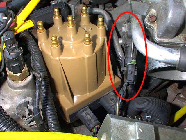
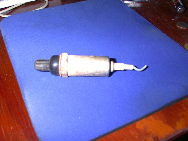
Oxygen Sensor (O2S)
The oxygen sensor is located in the exhaust manifold and produces a voltage signal proportional to the content of oxygen in the exhaust. A higher oxygen content across the sensor tip will vary the oxygen differential, thereby lowering the sensor's output voltage. On the other hand, lower oxygen content will raise the output voltage. Typically the voltage ranges from 0.10 volts (lean) to 0.90 volts (rich). The computer uses the sensor's input voltage to adjust the air/fuel mixture, leaning it out when the sensor detects a rich condition or enriching it when it detects a lean condition. The ideal stoichiometric fuel/air ratio (14.7:1) will produce about 0.45 volts. Checking the O2S.- Start the engine and let it idle. With a voltmeter check the voltage at the O2S wire (purple color). It should stay at approx. 0.2 volts. Wait 2-3 minutes, until it gets to normal operating temperature. The voltage should fluctuate between 0.1 and 0.9 volts. If the voltage doesn't fluctuate, or it does but it is slow to respond, the sensor is not working properly and should be replaced.
Mass Air Flow sensor (MAF)
The MAF sensor is positioned in the air intake duct, and it measures the amount of air entering the engine, so the computer can calculate how much fuel is needed to maintain the correct fuel/air mixture. The MAF sensor has no moving parts. It uses an electrical current to measure airflow. Checking the MAF.- The MAF of the Chevrolet Cavalier, has three wires: supply (orange), signal (brown), and ground (black). With the ignition key On check for 12 volts on the supply wire, 2.5 volts at the signal wire, and for a good ground at the ground wire. Start the engine, and measure the frequency on the signal wire, it should vary between 0 and 150 Hz. (Not every multimeter has this function). The frequency should increase as you accelerate, and decrease at idle.
Coolant Temperature Sensor (ECT)
The ECT measures the temperature of the engine coolant, so the computer can adjust the mixture when the engine is cool or hot. The ECT is located near the thermostat. Checking the ECT: The ECT has two wires, the signal wire (yellow), and the ground wire (black). Turn the ignition key On. With the connector unplugged, you should get 5 volts in the signal wire, and 0 volts in the ground wire. Plug the connector and start the engine. The voltage should decrease as the engine gets hot. If the voltage doesn't change, the sensor is defective.
|